Focus Companies
Aerfor Srl
• 06.05.2015
This article is over 3 years old
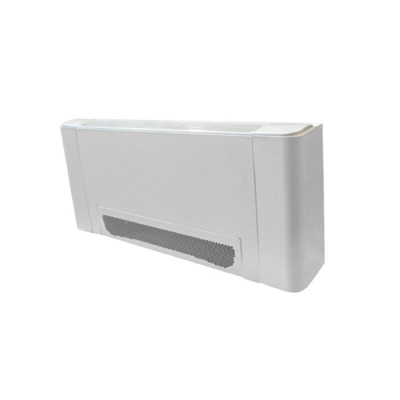
FIPA: The revolutionary fancoil
The italian company Aerfor developed the first Fancoil where the main components are assembled like in a little air handling unit.
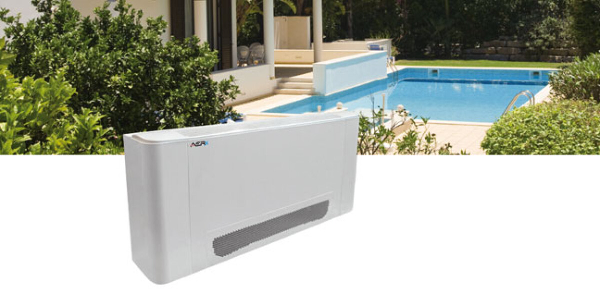
A fancoil is an appliance designed to condition air in rooms. It is mainly made of a fan blowing air onto an heat exchanger (coil). It gives heat or cool depending on the temperature of the liquid flowing into the heat exchanger.
The liquid in the pipes is supplied by a centralised source of chill water (chiller) or from a source of warm water (boiler or heat pump). In case that the water is cold the humidity in the air condenses on the exposed surfaces of the coil thereby dehumidifying the air in the room.
Main components: Fan-Motor-Heat exchanger (coil)-Cabinet
Goals to achieve with a good fancoil:
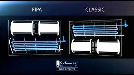
The main components are assembled in FIPA like in a little air handling unit.
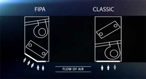
The classical fancoil unit has the fan blowing onto the coil. See the picture here below, showing the conic track of the air (concentrated in a limited area of the coil), the high velocity of the air on the outlet of the blowers and the high internal resistance of the unit PL (Pressure Loss, function of the square of the velocity); remember the formula:

where PL is the Pressure Loss, ρ is the air density, V² indicates the square of the velocity, S is the surface of the coil, and Cp is the coefficient depending on the shape of the coil and on the angle of the air flowing on the coil.
The high velocity and turbulence of a classic fancoil imply a higher pressure loss [PL in Pascal (Pa)] and less airflow on the outlet compared to FIPA.
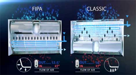
Classic FCU – The picture shows the air passing through the filter, the fans and the coil, going out of the grilles in the room . From warm (27°C-red) it gets colder to about 14°C. The water going into the coil at 7 °C and coming out at higher temperature (12°C).
FIPA FCU – The pictures 2 and 4 show the air passing through a larger filter, the coil and the fans, going out of the grilles in the room. The passing through the coil of the air is homogenously distributed on a larger surface (through all the coil, even in the corners). The air flows through at a lower velocity (less noise) and gets out colder, at about 12,5°C.
The liquid in the pipes is supplied by a centralised source of chill water (chiller) or from a source of warm water (boiler or heat pump). In case that the water is cold the humidity in the air condenses on the exposed surfaces of the coil thereby dehumidifying the air in the room.
How is a classic FCU made

Main components: Fan-Motor-Heat exchanger (coil)-Cabinet
Goals to achieve with a good fancoil:
- Uniform exploitation of the surface of the exchanger;
- Suitable air flows depending on operating conditions;
- Good condensate isolation;
- Simple condensate drainage;
- Adjustment of water flow in the exchanger;
- Working as silent as possible;
- Reversible water connections on work;
- Efficient air filtration;
- Control system integration;
- Easy maintenance.
What makes FIPA different
The main components are assembled in FIPA like in a little air handling unit.


The classical fancoil unit has the fan blowing onto the coil. See the picture here below, showing the conic track of the air (concentrated in a limited area of the coil), the high velocity of the air on the outlet of the blowers and the high internal resistance of the unit PL (Pressure Loss, function of the square of the velocity); remember the formula:

where PL is the Pressure Loss, ρ is the air density, V² indicates the square of the velocity, S is the surface of the coil, and Cp is the coefficient depending on the shape of the coil and on the angle of the air flowing on the coil.
The high velocity and turbulence of a classic fancoil imply a higher pressure loss [PL in Pascal (Pa)] and less airflow on the outlet compared to FIPA.

Classic FCU – The picture shows the air passing through the filter, the fans and the coil, going out of the grilles in the room . From warm (27°C-red) it gets colder to about 14°C. The water going into the coil at 7 °C and coming out at higher temperature (12°C).
FIPA FCU – The pictures 2 and 4 show the air passing through a larger filter, the coil and the fans, going out of the grilles in the room. The passing through the coil of the air is homogenously distributed on a larger surface (through all the coil, even in the corners). The air flows through at a lower velocity (less noise) and gets out colder, at about 12,5°C.
The plus of FIPA
- Wider air suction surface;
- Lower internal pressure loss;
- Higher airflow;
- Lower noise level;
- Higher capacity;
- Energy saving (the motor turns more “relaxed” and consumes less energy);
- FIPA is cheaper because man can get more capacity with a little size;
- Easier installation – Removing the flanks the installer has access to all he needs;
- Quicker maintenance – Inspection or cleaning the filter does not need to remove the cabinet and can be made by one technician only. Half time, half cost;
- Versatile control. FIPA has a wide range of controls, with weekly programmer, safety devices, window contact, double daily settings and can be connected to a centralized system;
- Wide range of models and sizes.
Available documents


