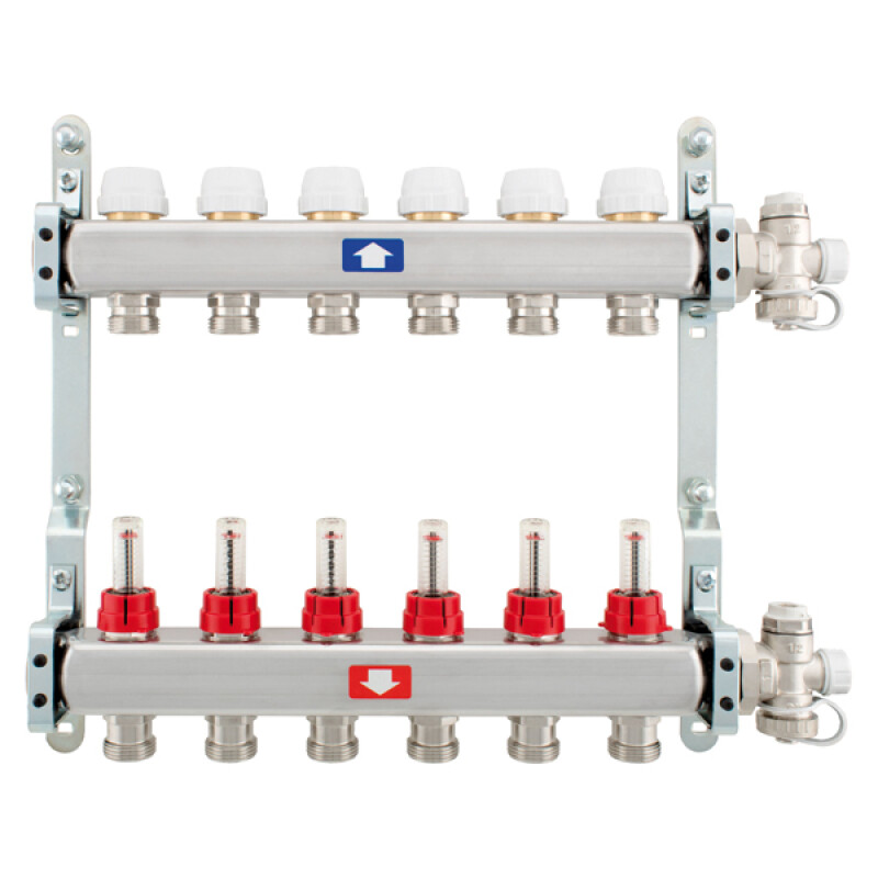


Stainless steel pre-assembled manifolds
High flow rate, high resistance to corrosion, installation in boxes with 90mm depth, suitable for heating systems.
Description
 ITAP SpA pre-assembled manifolds are used to distribute heat-transfer fluid inside a system. They can be used in traditional radiator systems, and innovative under-floor radiant systems. As ITAP SpA manifolds are made with stainless steel, they are particularly suitable for heating systems. If used in cooling systems, they must be suitably insulated to avoid the formation of condensation on their outer surface. The use of ITAP SpA manifolds also allows all of the project parameters to be controlled, providing the perfect balance of each outlet. This avoids any unnecessary waste and ensures an elevated level of thermal comfort. In the complete version, the manifolds are equipped with flow rate regulation valves (flow meters), with preset cut-off valves set-up for electro-thermal actuator-control and with drain and air vent units. As an alternative to flow meters, it is possible to request the installation of regulation lockshields. Thanks to their increased cross-section, the bars that comprise the flow and return manifolds allow elevated flow rate values to be obtained. If necessary, a differential by-pass can be installed between the flow and return manifolds: this reduces any overpressure in the circuits to a minimum, protecting the service life of all of the parts and avoiding bothersome noises in the rooms where the heating system is installed. ITAP SpA manifolds, available with 1” main connections, can be housed in 90mm-deep metal boxes. This provides an extremely significant advantage: boxes having a similar depth can be positioned not only in the perimeter walls of the building, but also in the inside dividing walls. This translates into maximum freedom of choice for designers and installation technicians.
 COMPONENTS
- AISI 304L stainless steel flow manifold, equipped with flow meters or regulation lockshields;
- AISI 304L stainless steel return manifold, equipped with cut-off valves set up for electro-thermal control;
- Ball valves CW617N nickel-plated brass, equipped with thermometer;
- End pieces with drain valve and air vent valve;
- Complete metal brackets, to install the pre-assembled manifold inside the metal box.
CONDITIONS OF USE
Required fluid: water (maximum admissible percentage of glycol: 30%).
Maximum operating pressure with installed flow meters: 6 bar.
Maximum operating pressure with installed lockshields: 10 bar.
Maximum operating temperature with installed flow meters: 70°C.
Maximum operating temperature with installed lockshields: 80°C.
Main ISO 228 connections: 1” .
Main centre-distance connections: 200 mm.
3 to 13 outlets with 3/4” Eurokonus connections.
Outlet centre-distance: 50 mm.
Flow meter regulation: 0-6 l/min.
Flow meter precision: +/- 10%.
BY-PASS
 This accessory is used to limit a rise in differential pressure inside the circuits, when electro-thermal actuators are installed on the return manifolds. When the various electro-thermal actuators close the outlet circuits, the differential pressure inside the system rises significantly, causing the noise level to increase and subjecting the various mechanical parts to increasingly greater stress. When this phenomenon occurs, the by-pass kit allows an overpressure drain outlet to open, connecting the flow manifold directly to the return one. In fact, the by-pass kit is equipped with a fixed setting spring check valve: when the differential pressure exceeds 25kPa (= 0.25 bar), the valve opens, connecting the flow manifold directly to the return one. As the differential pressure increases, the check valve opens proportionally, as shown in the following diagram.
INSTALLATION
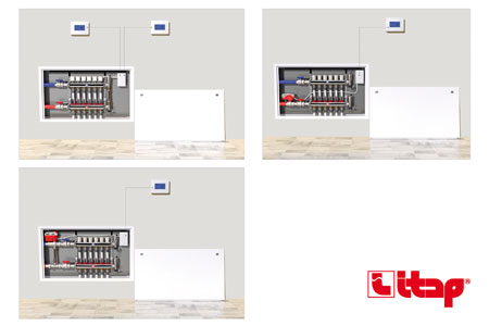
The ITAP SpA pre-assembled manifolds are installed in metal boxes Art. 498, with a max depth of 90 mm. Accordingly, this type of installation is not only possible along the perimeter walls of the building, but also in the indoor dividing walls. Thanks to this distinguishing feature, maximum freedom applies to installation inside buildings. In order to control the temperature of every single room, it is advisable to use pre-assembled manifolds combined with electro-thermal actuators Art. 891M. These actuators provide maximum flexibility in terms of temperature control: a room thermostat can be connected to each actuator, stopping the flow of heat transfer fluid when the project temperature of the individual room is reached. Accordingly, the thermal comfort of each room is controlled independently. To balance every circuit, the flow manifold outlets require the installation of a micro-metric valve, equipped with a flow meter [fig.1]. Accordingly, it is possible to regulate the flow rate by simply turning the transparent part of the valve until the project flow rate is reached (read directly on the graduated scale of the valve). ITAP SpA flow meters are also equipped with regulation protection: it is in fact possible to lock the micro-metric valve in its open position, using the standard-supply red cover. If, due to debris in the circuit, the transparent part of the flow meter does not guarantee the correct reading of the graduated scale, simply close this valve to remove the transparent part and clean it thoroughly, without losing any water from the system. If no direct reading of the project flow rate is required, it is possible to request regulation lockshields to be installed on the flow manifold instead of flow meters.

If, for the design, it is not necessary to control the thermal comfort of every room independently, it is advisable to install ITAP SpA pre-assembled manifolds with motorised ball zone valves Art. 980, 981, 984+988.If these valves are driven by servomotors Art. 989, 990, 991 and connected to a room thermostat, they can stop the flow of heat transfer fluid feeding into the manifold, when the thermostat reaches the set temperature. The use of motorised zone valves is particularly useful when the thermal system of a dwelling is divided into two zones. Typically, in the most common projects, it is necessary to manage two individual zones: a day zone and a night zone. Thanks to the installation of two pre-assembled manifolds, each with a motorised zone valve, it will be possible to control each zone independently, by simply connecting a room thermostat to the aforementioned valves.
Technical features
Applications


